
Page 33 - SKF-SPEEDI-SLEEVE
P. 33
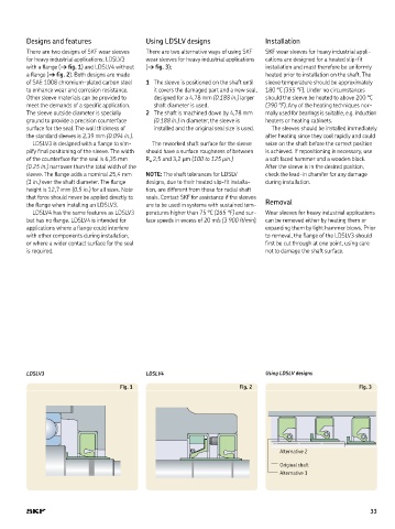
Designs and features                Using LDSLV designs                 Installation
         There are two designs of SKF wear sleeves    There are two alternative ways of using SKF   SKF wear sleeves for heavy industrial appli-
         for heavy industrial applications; LDSLV3    wear sleeves for heavy industrial applications   cations are designed for a heated slip-fit
         with a flange († fig. 1) and LDSLV4 without   († fig. 3);               installation and must therefore be uniformly
         a flange († fig. 2). Both designs are made                              heated prior to installation on the shaft. The
         of SAE 1008 chromium-plated carbon steel   1  The sleeve is positioned on the shaft until   sleeve temperature should be approximately
         to enhance wear and corrosion resistance.   it covers the damaged part and a new seal,   180 °C (355 °F). Under no circumstances
         Other sleeve materials can be provided to   designed for a 4,78 mm (0.188 in.) larger   should the sleeve be heated to above 200 °C
         meet the demands of a specific application.   shaft diameter is used.   (390 °F). Any of the heating techniques nor-
         The sleeve outside diameter is specially   2  The shaft is machined down by 4,78 mm   mally used for bearings is suitable, e.g. induction
         ground to provide a precision counterface   (0.188 in.) in diameter, the sleeve is   heaters or heating cabinets.
         surface for the seal. The wall thickness of    installed and the original seal size is used.  The sleeves should be installed immediately
         the standard sleeves is 2,39 mm (0.094 in.).                            after heating since they cool rapidly and could
           LDSLV3 is designed with a flange to sim-  The reworked shaft surface for the sleeve   seize on the shaft before the correct position
         plify final positioning of the sleeve. The width   should have a surface roughness of between   is achieved. If repositioning is necessary, use
         of the counterface for the seal is 6,35 mm   R a  2,5 and 3,2 µm (100 to 125 µin.)  a soft faced hammer and a wooden block.
         (0.25 in.) narrower than the total width of the                         After the sleeve is in the desired position,
         sleeve. The flange adds a nominal 25,4 mm   NOTE: The shaft tolerances for LDSLV   check the lead-in chamfer for any damage
         (1 in.) over the shaft diameter. The flange   designs, due to their heated slip-fit installa-  during installation.
         height is 12,7 mm (0.5 in.) for all sizes. Note   tion, are different from those for radial shaft
         that force should never be applied directly to   seals. Contact SKF for assistance if the sleeves
         the flange when installing an LDSLV3.  are to be used in systems with sustained tem-  Removal
           LDSLV4 has the same features as LDSLV3   peratures higher than 75 °C (165 °F) and sur-  Wear sleeves for heavy industrial applications
         but has no flange. LDSLV4 is intended for   face speeds in excess of 20 m/s (3 900 ft/min).  can be removed either by heating them or
         applications where a flange could interfere                             expanding them by light hammer blows. Prior
         with other components during installation,                              to removal, the flange of the LDSLV3 should
         or where a wider contact surface for the seal                           first be cut through at one point, using care
         is required.                                                            not to damage the shaft surface.


         LDSLV3                              LDSLV4                              Using LDSLV designs

                                     Fig. 1                              Fig. 2                              Fig. 3


                                                                                     Alternative 2
                                                                                     Original shaft
                                                                                     Alternative 1


                                                                                                                 33