Page 86 - SKF-bearing-housings
P. 86

Split plummer block housings SNL 2, 3, 5 and 6 series

             Mounting                                                        Table 13
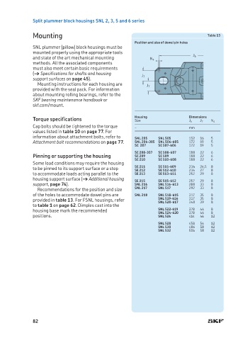
                                                  Position and size of dowel pin holes
             SNL plummer (pillow) block housings must be
             mounted properly using the appropriate tools
             and state of the art mechanical mounting   N 4            J 6
             methods. All the associated components
             must also meet certain basic requirements
             († Specifications for shafts and housing
              support surfaces on page 45).          J 7
               Mounting instructions for each housing are
                                                       J 7
             provided with the seal pack. For information
             about mounting rolling bearings, refer to the
             SKF bearing main tenance handbook or
             skf.com/mount.
             Torque specifications                Housing             Dimensions  N 4
                                                  Size
                                                                      J 6
                                                                          J 7
             Cap bolts should be tightened to the torque   –          m m
             values listed in table 10 on page 77. For
               information about attachment bolts, refer to   SNL 205  SNL 505  1 5 2  1 6  5
             Attachment bolt recommendations on page 77.  SNL 206-305  SNL 506-605  1 7 2  1 9  5
                                                  SE  207  SE 507-606  1 7 2  1 9  5
                                                  SE 208-307  SE 508-607  1 8 8  2 2  6
             Pinning or supporting the housing    SE 209   SE 509     1 8 8  2 2  6
                                                  SE 210   SE 510-608  1 8 8  2 2  6
             Some load conditions may require the housing
             to be pinned to its support surface or a stop   SE 211  SE 511-609  2 34  24,5 8
                                                                      234
                                                           SE 512-610
                                                  SE 212
                                                                          27
                                                                              8
             to accommodate loads acting parallel to the   SE 213  SE 513-611  252  29  8
             housing support surface († Additional housing   SE 215  SE 515-612  257  29  8
             support, page 74).                   SNL 216  SNL 516-613  288  33  8
               Recommendations for the position and size   SNL 217  SNL 517  292  33  8
             of the holes to accommodate dowel pins are   SNL 218  SNL 518-615  317  35  8
             provided in table 13. For FSNL housings, refer   SNL 519-616  317  35  8 8
                                                                          39
                                                           SNL 520-617
                                                                      348
             to table 1 on page 62. Dimples cast into the
             housing base mark the recommended             SNL 522-619  378  44  8 8
                                                                      378
                                                                          44
                                                           SNL 524-620
             positions.                                    SNL 526    414  46  12
                                                           SNL 528    458  54  12
                                                           SNL 530    486  58  12
                                                           SNL 532    506  58  12


             82
   81   82   83   84   85   86   87   88   89   90   91