
Page 402 - Rollingbearings
P. 402
3 Angular contact ball bearings
Calculating the axial Load carrying
load for bearings capacity of bearing
mounted singly or pairs
paired in tandem The values for basic load ratings and fatigue
load limits listed in the product tables, page
When a radial load is applied to a single row 406, apply to single bearings For bearing
angular contact ball bearing, the load is pairs mounted immediately adjacent to each
3 transmitted from one raceway to the other at other, the following values apply:
an angle to the bearing axis and an internal
axial load is induced This must be con- • basic dynamic load rating for standard
sidered when calculating the equivalent bearings in all arrangements and for SKF
bearing loads for bearings in adjusted Explorer bearings in a back-to-back or
arrangements consisting of two single bear- face-to-face arrangement
ings and/or bearing pairs arranged in C = 1,62 C single bearing
tandem • basic dynamic load rating for SKF Explorer
The equations (table 11) are only valid if bearings in a tandem arrangement
the bearings have identical contact angles C = 2 C single bearing
and are adjusted against each other to prac- • basic static load rating
tically zero clearance, but without any C = 2 C 0 single bearing
0
preload In the table, bearing A is subjected • fatigue load limit
to a radial load F and bearing B to a radial P = 2 P u single bearing
u
rA
load F Both F and F are always con-
rB
rA
rB
sidered positive, even when they act in the
direction opposite to that shown in the ig-
ures The radial loads act at the pressure
centres of the bearings (distance a, refer
to product tables, page 406)
These calculations can easily be done with
SKF’s online calculation tools When the
bearings are adjusted with clearance or
preload, or when bearings with different
contact angles are used, the equations
become more complex and can be done
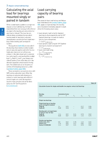
using the SKF SimPro platform Table 10
(skf com/simpro) Calculation factors for single and double row angular contact ball bearings
Bearing Calculation factor
types e X Y 1 Y 2 Y 0
Single row bearings
Single bearings or bearing
pairs arranged in tandem
Sufix B 1,4 0,35 – 0,57 0,26
Sufix AC 0,68 0,41 – 0,87 0,38
Bearing pairs arranged back-
to-back or face-to-face
Sufix B 1,14 0,57 0,55 0,93 0,52
Sufix AC 0,68 0,67 0,92 1,41 0,76
Double row bearings
Series 32 A, 33 A 0,8 0,63 0,78 1,24 0,66
Series 33 D 1,34 0,54 0,47 0,81 0,44
Series 33 DNRCBM 1,14 0,57 0,55 0,93 0,52
400