
Page 175 - SKF-bearing-housings
P. 175
Design considerations
For housings made of spheroidal graphite pinned to the support surface or a stop should
cast iron, the values obtained from table 7 be provided to counter the load. The dowel
should be multiplied by a factor of 1,8. pins or stop should be sufficiently strong to
The load P a is the axial breaking load of the accommodate the loads acting parallel to the
housing. If the incorporated bearing is mounted support surface.
on a sleeve, check the permissible axial load Recommendations for the position and size
for the sleeve. of the holes to accommodate dowel pins are 4
provided in table 11 on page 177.
Additional housing support
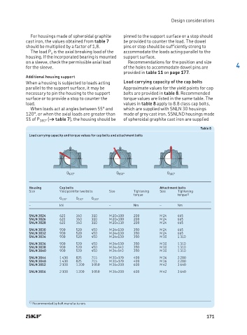
When a housing is subjected to loads acting Load carrying capacity of the cap bolts
parallel to the support surface, it may be Approximate values for the yield points for cap
ne cessary to pin the housing to the support bolts are provided in table 8. Recommended
surface or to provide a stop to counter the torque values are listed in the same table. The
load. values in table 8 apply to 8.8 class cap bolts,
When loads act at angles between 55° and which are supplied with SNLN 30 housings
120°, or when the axial loads are greater than made of grey cast iron. SSNLND housings made
5% of P 180° († table 7), the housing should be of spheroidal graphite cast iron are supplied
Table 8
Load carrying capacity and torque values for cap bolts and attachment bolts
Q 120° Q 150° Q 180°
Housing Cap bolts Attachment bolts
Size Yield point for two bolts Size Tightening Size Tightening
torque torque 1)
Q 120° Q 150° Q 180°
– kN – Nm – Nm
SNLN 3024 620 360 310 M 20¥100 200 M 24 665
SNLN 3026 620 360 310 M 20¥100 200 M 24 665
SNLN 3028 620 360 310 M 20¥110 200 M 24 665
SNLN 3030 900 520 450 M 24¥130 350 M 24 665
SNLN 3032 900 520 450 M 24¥130 350 M 24 665
SNLN 3034 900 520 450 M 24¥130 350 M 30 1 310
SNLN 3036 900 520 450 M 24¥130 350 M 30 1 310
SNLN 3038 900 520 450 M 24¥140 350 M 30 1 310
SNLN 3040 900 520 450 M 24¥140 350 M 30 1 310
SNLN 3044 1 430 825 715 M 30¥170 400 M 36 2 280
SNLN 3048 1 430 825 715 M 30¥170 400 M 36 2 280
SNLN 3052 2 100 1 200 1 050 M 36¥200 600 M 42 3 640
SNLN 3056 2 100 1 200 1 050 M 36¥200 600 M 42 3 640
1) Recommended by bolt manufacturers
171