
Page 161 - SKF-bearing-housings
P. 161
Standard housing design
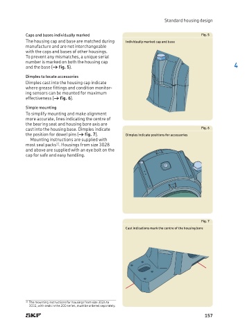
Caps and bases individually marked Fig. 5
The housing cap and base are matched during Individually marked cap and base
manufacture and are not interchangeable
with the caps and bases of other housings.
To prevent any mismatches, a unique serial
number is marked on both the housing cap
and the base († fig. 5). 4
Dimples to locate accessories
Dimples cast into the housing cap indicate
where grease fittings and condition monitor-
ing sensors can be mounted for maximum
effectiveness († fig. 6).
Simple mounting
To simplify mounting and make alignment
more accurate, lines indicating the centre of
the bearing seat and housing bore axis are
cast into the housing base. Dimples indicate Fig. 6
the position for dowel pins († fig. 7). Dimples indicate positions for accessories
Mounting instructions are supplied with
1)
most seal packs . Housings from size 3028
and above are supplied with an eye bolt on the
cap for safe and easy handling.
Fig. 7
Cast indications mark the centre of the housing bore
1) The mounting instructions for housings from size 3024 to
3032, with seals in the 200 series, must be ordered separately.
157